← Back to rubinobservatory.org

Technical Details

Focal Plane Requirements

  • High QE to 1000nm
  • Thick silicon (> 100 µm)
  • PSF << 0.7 arcseconds
    • High internal field in the sensor
    • High resistivity silicon substrate (> 5 kohm/cm)
    • High applied voltages (40 - 50 Volts)
    • Small pixel size (0.2 arcseconds = 10 µm)
  • Fast f/1.2 focal ratio
    • Sensor flatness < 5µm p-v
    • Package with piston, tip, tilt adj. to ~1µm
  • Wide Field of View
    • ~ 3200 square cm focal plane
    • > 189-sensor mosaic (~16 square cm each)
    • Industrialized production processes
  • High throughput
    • > 90% fill factor. 4-side buttable package, sub-mm gaps
  • Fast readout (2 sec)
    • Segmented sensors (3024 total output ports )
    • 150 connections per sensor
  • Low read noise
    • < 10 electrons

Focal Plane Design

  • FPA is 189 4K x 4K CCDs, each with 16 outputs
    • 3024 video channels/FPA total
  • Sensors organized into identical rafts of 3 x 3 sensors
  • Clocking of Science CCDs is synchronous and global throughout the FPA
    • 500 kpix/sec * 16 outputs/CCD * 189 CCDs = 3.2 Gpix/2sec
  • A raft is an autonomous object and can function as a complete camera
    • 144 channels/raft
    • readout electronics fit in "shadow" of sensors
  • Raft functions as a dumb slave to OCS
  • 16-bit dynamic range is handled by a single-gain readout

Camera Data Rates

  • Over 3 GBytes/sec peak raw data from camera
  • 1 pixel = 2 Bytes (raw)
  • 3.2 billion pixels read out in 2 sec (15 sec integration)
  • Dynamic Range: 18 bits / pixel
  • > 0.6 GB/sec average in pipeline
  • ∼15 TBytes/night
  • 2 TFlops/s average, 9 TFlops/s peak

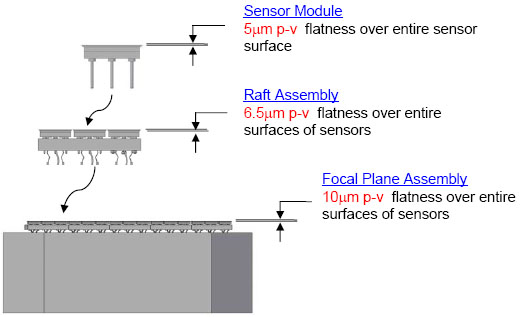
FPA Flatness Allocations Established

Measurements of the required flatness of the focal plane array, from indivdual CCD elements to rafts to the entire array. Flatness affects consistency of focus.

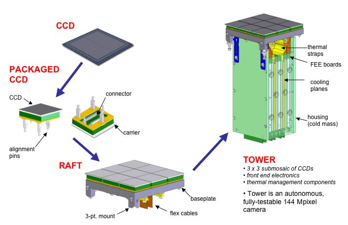
Sensor to Raft/Tower Configuration

To create the LSST camera's focal plane array, 21 rafts, each comprising 189 CCDs, are mounted on towers containing the necessary electronics, and the towers are assembled into one unit.

Schematic of Camera Control System

A schematic outlining the camera control system.

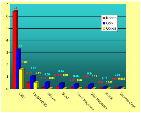
Comparison of Wide Field Camera Controllers

Comparison of wide-field camera controller capabilities across several astronomical CCD cameras.

Changer/Carousel Design

  • Carousel holds five filters:g-r-i-z-y
  • Rail-type changer engages carousel for automatic changing; 
  • Maximum filter change time of two minutes;
  • Can change filters up to four times per night; 
  • Manual load-lock changer for inserting a 6th filter (u-filter);
  • Operational lifetime of 2 x 10⁴ cycles

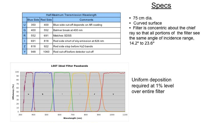
LSST Ideal Filter Curves and Specifications

Table of LSST ideal filter curves and specifications.

Camera Thermal Zones

The LSST camera has three separate thermal zones as indicated in this illustration.

Image Credit: 
All images LSST / DOE

Financial support for Rubin Observatory comes from the National Science Foundation (NSF) through Cooperative Agreement No. 1258333, the Department of Energy (DOE) Office of Science under Contract No. DE-AC02-76SF00515, and private funding raised by the LSST Corporation. The NSF-funded Rubin Observatory Project Office for construction was established as an operating center under management of the Association of Universities for Research in Astronomy (AURA).  The DOE-funded effort to build the Rubin Observatory LSST Camera (LSSTCam) is managed by the SLAC National Accelerator Laboratory (SLAC).
The National Science Foundation (NSF) is an independent federal agency created by Congress in 1950 to promote the progress of science. NSF supports basic research and people to create knowledge that transforms the future.
NSF and DOE will continue to support Rubin Observatory in its Operations phase. They will also provide support for scientific research with LSST data.   


Contact   |   We are Hiring

Admin Login

Back to Top